01 / Abstract
Abstract
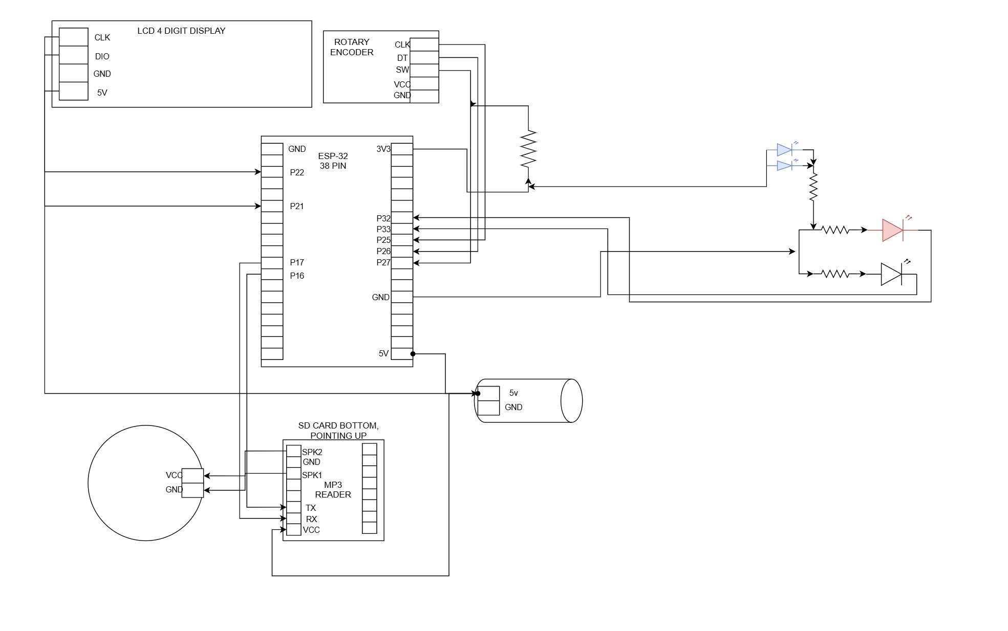
This project turns an existing R2D2 controller wiring diagram into a reproducible PCB. The work begins with source preservation and firmware pin verification, then proceeds through schematic capture, electrical review, layout, fabrication planning, and board-level test.
02 / Use cases
Use cases
- Replace fragile point-to-point wiring with a repeatable controller board.
- Preserve the electrical design independently of temporary screenshots and hosted tools.
- Demonstrate a complete pinout-to-fabrication engineering workflow.
03 / Theory
Operating theory
Voltage domains
The ESP32 uses 3.3 V logic while the display and audio modules may operate from 5 V. Every interface must be checked for input thresholds, pullups, and back-powering paths.
Interface integrity
Rotary encoder, display, UART, LED, and speaker connections have different loading and noise behavior. The schematic must preserve signal direction and keep differential speaker outputs away from logic ground assumptions.
Design verification
Firmware pin assignments provide strong evidence for GPIO mapping, but footprints, resistor values, current demand, and connector orientation still require physical verification.
04 / Requirements
Requirements and success criteria
- Capture every ESP32 GPIO assignment with a confidence level.
- Identify connector pinouts, voltage rails, resistor values, and physical footprints.
- Run electrical-rule checks before board routing.
- Produce a schematic, board outline, bill of materials, test plan, and unresolved-assumption list.
05 / Architecture
System architecture
06 / Current status
Current status
The source image is preserved, firmware GPIO assignments have been cross-checked, and a first-pass net table exists. Electrical and mechanical details remain unverified, so schematic capture is not yet complete.
07 / Next steps
Next steps
- Confirm whether the PCB carries an ESP32 development board or a bare module.
- Identify exact module and connector footprints.
- Verify display signal order and logic-voltage compatibility.
- Select LED current-limiting values and draft the schematic.
- Run an electrical design review before routing.
08 / Risks
Risks and constraints
- A 5 V pullup or module output could overstress an ESP32 GPIO.
- Image-only assumptions could produce reversed connectors or incorrect footprints.
- The speaker output is differential and must not be treated as ground-referenced audio.
09 / Artifacts
Engineering artifacts
- Preserved source pinout
- Firmware GPIO cross-check
- First-pass net table
- Planned schematic, PCB, BOM, and test report